

研究背景
电子皮肤在机器人、人工智能、人机界面和健康监测方面具有各种重要的潜力。为了真正模仿人类皮肤,电子皮肤需要具备以下特性。首先,电子皮肤提供多功能的传感能力,如应变、压力、剪切力、温度和湿度传感能力。其次,电子皮肤应该是柔软和可拉伸的,因为人类皮肤需要很好地适应身体运动,同时仍然保持其各种传感功能。此外,可拉伸的导体,即在拉伸过程中其导电性能保持不变的导体,是作为电子皮肤系统中可拉伸电路的另一个重要组成部分。第三,除了上述传感功能外,人类皮肤还具有自愈能力。因此,自愈能力成为电子皮肤的一个绝对必要的功能,它可以大大延长电子皮肤的使用寿命。
研究成果
在这篇综述中,杭师大朱雨田教授联合美国田纳西大学郭占虎教授从不同方面总结了电子皮肤的进展,主要回顾了电子皮肤的基本功能,包括多功能的感应能力,如应变、压力、剪切力、温度和湿度感应,以及其他功能,包括电子皮肤的自我修复能力、可拉伸性和透明度。在每一节中, 系统地总结了所使用的材料、实施机制和实现每个单独功能的策略。随后,总结了一些具有微妙集成设计的电子皮肤的主要进展和应用。最后,讨论了该领域的开放问题和未来的挑战。相关研究以“Recent Progress in Essential Functions of Soft Electronic Skin”为题发表在Advanced Functional Materials期刊上。
图文导读

Figure 1. a) Schematic illustration of fabrication of PDMS based strain sensor containing an Au micromesh. b) Optical micrograph of Au microwire network embedded in PDMS with high interconnectivity. c) SEM image for the Au microwire network embedded in PDMS. d) Dependence of resistance of the device with the applied strain. e) Resistance versus time during cycling tests at different strain to observe repeatability of the device. f) SEM images of the micro-cracks at different strains (0%, 0.5%, and 1%, respectively). g) Corresponding Finite-element method modeling results of the morphological evolution of micro-cracks at different strains (0%, 0.5%, and 1%, respectively). h) Variation of the relative resistance change of the cracks-based sensor with the applied strain. i) Variation of the relative resistance change of the cracks-based sensor with time during loading–unloading test at different final strains (0.5%, 1%, and 2%).
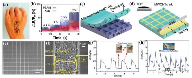
Figure 2. a) The pattern of graphene with the Schrodinger equation encapsulated within the stretchable device via the laser scribing technique, indicating that this technique could print any stretchable conductive pattern. b) Variation of the relative resistance change of the patterned sensors under various cyclic strains at a frequency of 0.5 Hz. c) Schematic diagram for the fabrication of PDMS film with mesh-like microtrenches by utilizing the preexisting pattern on Si template. d) Schematic diagram for filling MWCNT ink into the mesh-like microtrenches of PDMS film to form the designed conductive network. e,f) SEM images of the fabricated strain sensor embedded with the designed MWCNT network. g,h) Time-dependent response of the relative resistance change of the sensor to the blinking eyes and pulse, respectively.
Figure 3. a) Schematic diagram for hierarchical network structures containing hydrogen bonding between polymer network and Fe3+. b) Image shows that the F-hydrogel can be well stretched. c) Images show that the F-hydrogel can be attached tightly on human skin surface. d) The change of LED brightness with the elongation of F-hydrogel connected in the electric circuit. e) Bending of finger attached with F-hydrogels sensor at different bending angles. d-1) Variation of the relative change of resistance of F-hydrogels sensor with the applied strain. e-1) Variation of the relative change of resistance of F-hydrogels sensor with the bending degree of the finger. f) 3D Structure of the F-hydrogels strain sensor. g) Demonstrative experiment of the hydrogels strain sensor to monitor the human pulse.
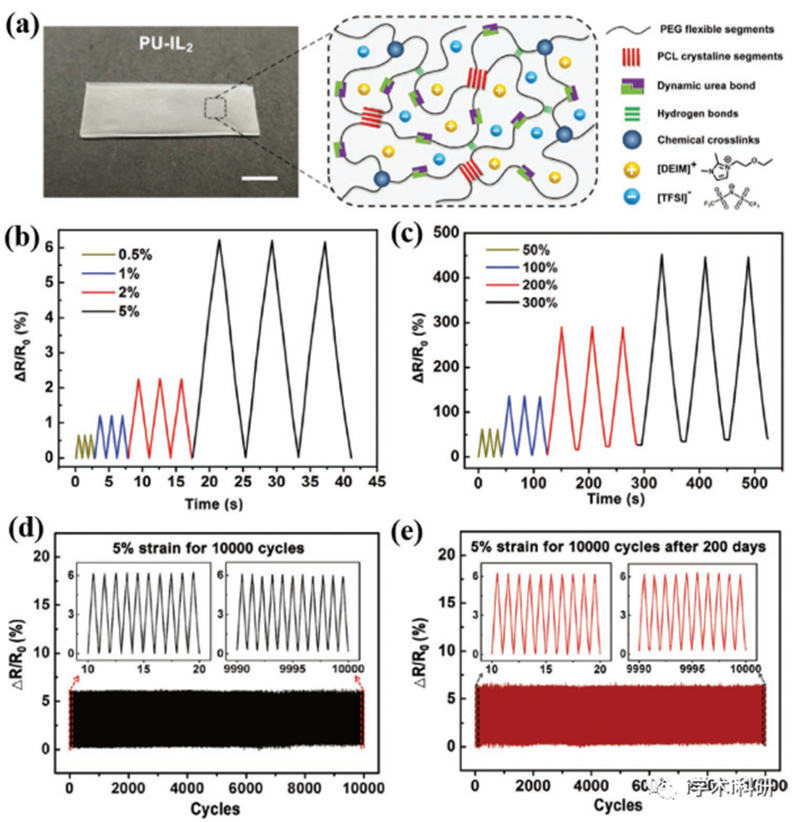
Figure 4. a) Image of PU-IL ionogel and its schematic diagram of inner structures. b,c) Relative resistance changes of PU-IL ionogel-based sensor as a function of strain under small strains and large strains, respectively. d) Long-term stretching-releasing cyclic test of the PU-IL ionogel-based sensor under a strain of 5% for 10 000 cycles. e) Long-term stretching-releasing cyclic test of the PU-IL ionogel-based sensor after being stored in open air for 200 days under a strain of 5% for 10 000 cycles.
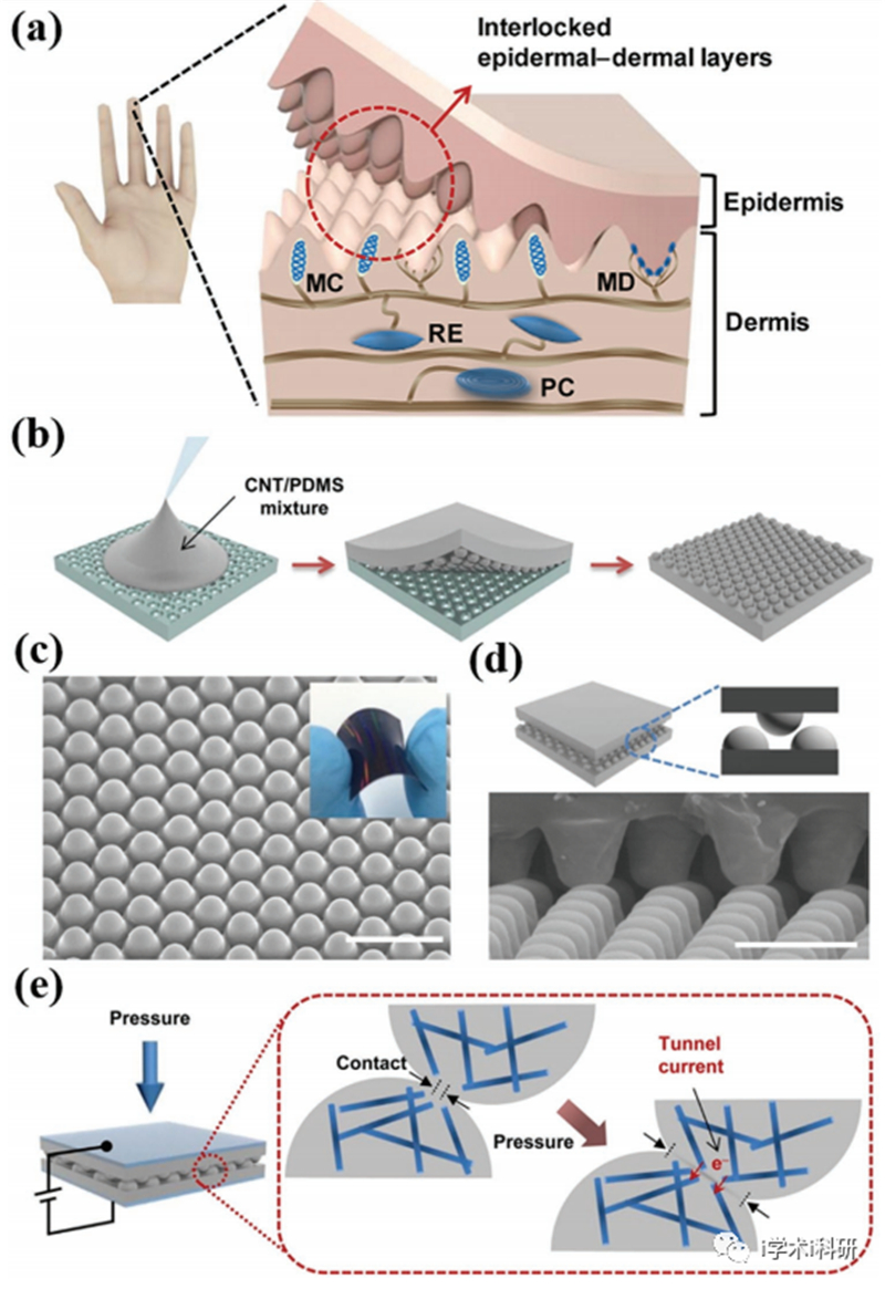
Figure 5. a) Schematic diagram of the human skin structure with the interlocked microstructure between the epidermal–dermal layers as well as various mechanoreceptors b) The fabrication of CNT/PDMS film with surface microstructures of hexagonal microdome arrays by using a silicon micromold as the template. c) SEM image of the CNT/PDMS film with the hexagonal microdome arrays. d) SEM image of the interlocked geometry by placing two microdome-patterned CNT/PDMS films together with patterned sides contacting each other. e) Schematic diagram of working principle of the pressure sensor.

Figure 6. a) Schematic diagram of the fabrication of metal-coated ZnO NWs on PDMS micropillars. b) Schematic diagram of the fabrication of the pressure sensor with the interlocked geometry by placing two PDMS films together with patterned sides contacting each other. c) Real-time response of the sensor showing the detection of a small droplet (0.58 Pa) on its surface. d) Real-time response of sound variations for different sound pressure levels.
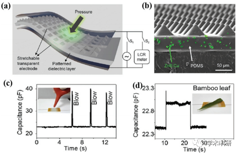
Figure 7. a) Schematic diagram of structure and circuit layout of the pressure sensor. b) Cross section SEM image showing the pyramidal microstructure on the PDMS dielectric layer. Real-time response of the sensor showing c) the detection of wind blow and d) 30 mg bamboo leaf.
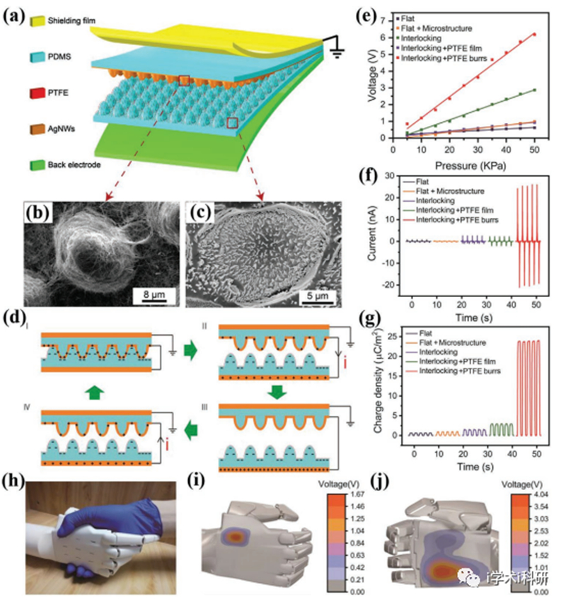
Figure 8. a) Schematic diagram of structures of the TENG sensor. b,c) The morphologies of top and bottom triboelectric layers, respectively. d) Schematic diagram of the working principle of TENG sensor: (I) Under pressure, equal amount of positive and negative charges are generated on top tribo-layers due to the different abilities of electron affinities. (II-III) The two tribo-layers are separated, electric current flows from top to bottom till the electric equilibrium is achieved. (IV) As the pressure is applied again, the two tribo-layers are close, electric current flows in the reverse direction. e) Comparisons of the pressure sensitivity for the sensors with different microstructures and surface conditions. f,g) Current and charge densities outputted from different sensors during cyclic loading with maximum pressures of 25 kPa. h–j) The demonstrative experiment of the TENG sensors to measure the handshaking pressure from human hands. In this experiment, the TENG e-skin sensors are adhered onto the surface of a bionic hand.
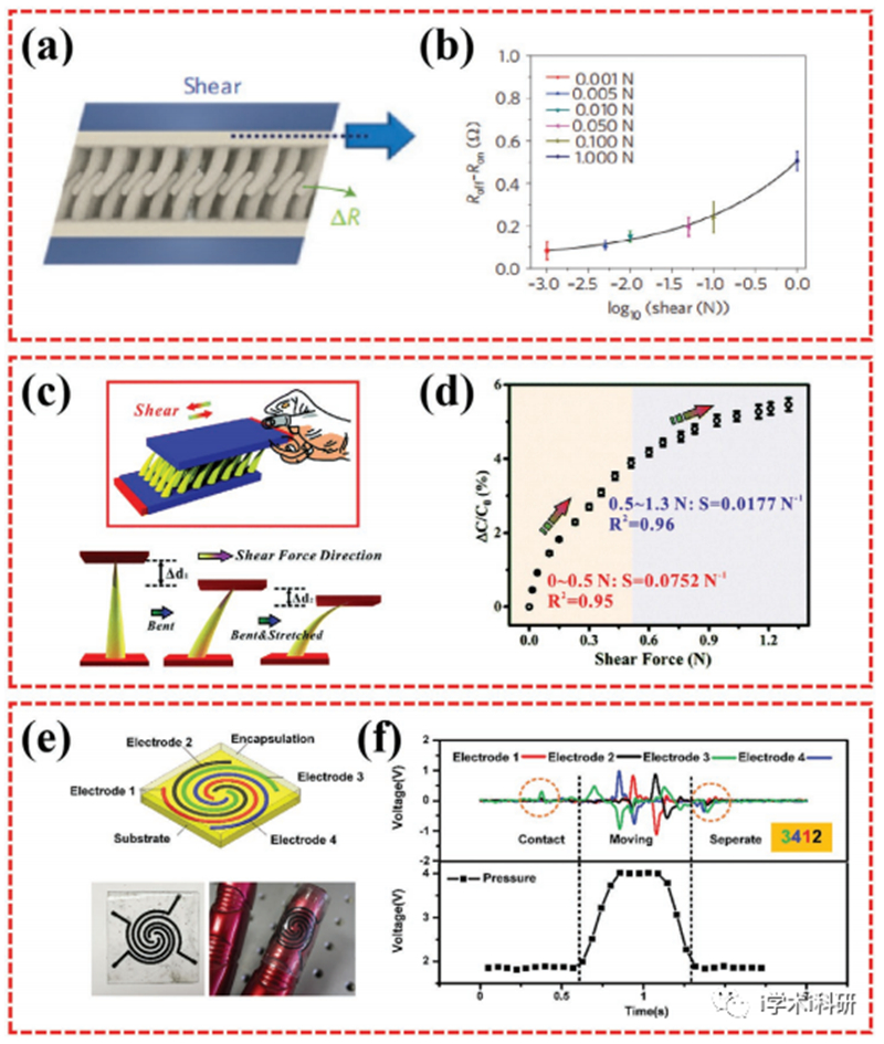
Figure 9. a) Schematic illustration of the shear force leading to the geometric distortions of the interlocked hairs. b) The change in the electrical resistance as a function of the applied shear force. c) Schematic illustration of the working principle of the capacitive-type sensor with spine arrays for shear force monitoring. d) Dependence of the capacitance variation on the applied shear force. e) Schematic diagram of the e-skin system with the fingerprint-like TENG on the surface of the sensor. f) Outputted signals from TENG and pressure sensor can reflect the complex action from (b).
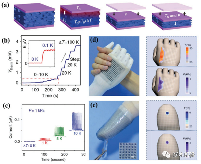
Figure 10. a) Schematics indicating the temperature and pressure sensing mechanisms of the MFSOTE sensor. b) Real-time response of a MFSOTE sensor to a biased temperature gradient range of 0–100 K. The inset in the figure shows the magnified signal of the sensor to a temperature gradient of 0.1 K. c) Real-time response of a MFSOTE sensor to a pressure of 1 kPa taken under various temperature differences (0, 1, 5, and 10 K). d) The demonstration experiment of a prosthetic hand arm adhered with MFSOTE-based-sensing array wrestling with an adult woman hand (left image) as well as the information of the temperature and pressure on a reconstructed map. e) The demonstration experiment of a fingertip covered with an inkjet-printed MFSOTE sensor matrix touching a tiny ice cube and the collection of the spatially resolved pressure and temperature information on a reconstructed map.
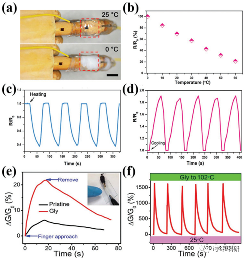
Figure 11. a) Optical images of DTG hydrogel-based sensor at 25 and 0 °C, respectively. b) Variation of the relative resistance change of DTG hydrogel[1]based sensor with temperature. c,d) Resistance of DTG hydrogel-based sensor during the heating or cooling, respectively. e) Real-time responses of hydrogel-based sensor and Gly-organohydrogel-based sensor to the approach of a finger, respectively. f) Variation of the relative resistance change of Gly-organohydrogel-based sensor in cyclic heating-cooling test ranged from 25 to 102 °C.
总结展望
在这篇综述中,作者概述了实现电子皮肤设备不同基本功能的一般策略,以及将这些通用功能整合到电子皮肤系统中的最新进展。随着材料科学和工艺技术的发展,在过去的十年中出现了大量的电子皮肤传感器。各种传感器已经很好地实现了人类皮肤的各个功能,如可伸展性、应变感应、压力感应、温度感应和自我修复能力。此外,一些新的制造和集成技术也被开发出来,将各种功能集成到一个设备中。尽管在软性电子皮肤方面已经取得了相当大的进展,但在这个问题上仍然存在许多挑战,限制了它的实际应用。
1.目前的技术仍然没有办法将这些传感器结合在一起而不造成相互干扰。目前,人们只能制造出由人类皮肤的部分功能组成的多功能集成电子皮肤系统。
2.只有非常有限的基于弹性体的、基于水凝胶的或基于离子凝胶的电子皮肤传感器一旦被损坏就能恢复其传感功能。然而,其他类型的电子皮肤传感器很难实现自愈能力,仍然缺乏一种通用的方法来实现多功能电子皮肤传感器的自愈功能。因此,这是未来电子皮肤需要解决的一个重要挑战。
3.大多数研究人员专注于设计各种传感器,缺乏电路设计和信号处理。因此,它需要来自不同领域的科学家的合作,包括化学、材料科学、工程和机电一体化等等,以解决这一挑战。
4.大多数报道的电子皮肤传感器都是在实验室里制作的。研究人员可能只追求传感器的功能和传感性能,而忽略了成本、生产效率和不良品率。电子皮肤的大面积和稳定生产仍然是困难的任务,这限制了电子皮肤的实际应用。
5.虽然天然皮肤不是透明的,但未来开发透明的电子皮肤是一个新的趋势,因为透明的结构有可能与显示元件和光伏电池集成。这使得电子皮肤不仅拥有各种传感能力,而且还具有显示功能。
6.整合除人类体感系统以外的其他传感功能,这可能使电子皮肤比天然皮肤更强大。
总之,开发可与人类皮肤媲美的高性能电子皮肤是一项系统工程,需要不同领域的努力。首先,各种类型的传感器是电子皮肤的重要组成部分,需要开发具有优良特性和与其他传感器更好兼容性的新传感器。目前,大多数电子皮肤的传感器都来自于可拉伸的电子导体,它们有一些不可避免的缺点,如不透明和不稳定。一些其他类型的可拉伸导体,如离子凝胶,可能是制造电子皮肤传感器的有希望的候选人。其次,当不同的电子皮肤组件结合在一起时,也需要一些精细的电路和结构设计,这需要材料科学和微电子科学的结合。
文献链接
Recent Progress in Essential Functions of Soft Electronic Skin, Adv. Funct. Mater. 2021, 31, 2104686, DOI: 10.1002/adfm.202104686.
https://doi.org/10.1002/adfm.202104686.
厦门柔性电子研究院
福建省协同创新院柔性电子产业技术分院
地址:厦门市集美区集美大道1995号科技成果转化加速器1期4F
邮编:361024 电话:0592-5366222 邮箱:admin@flex-elec.com
部分图片来源于网络,如有侵权请联系删除